
 Luminous box shown in proper alignment
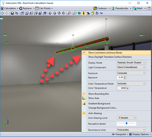
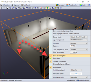
ElumTools can display the luminous area of the luminaire in the rendered view. Called the "Luminous Box," this is the actual luminous volume from the IES photometric file and its aiming as seen by ElumTools. The luminous box is outlined in bright green.
If the luminous box appears to be of a different size or does not coincide with the luminaire symbol in the rendered environment, return to the ElumTools Luminaire Manager and select the Light Source tab to examine the "Size and Shape." It may need to be resized or the family light source position revised for accurate calculations. This is very important.
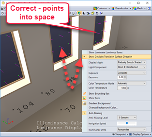
Glazing orientation can be seen by selecting "Show Daylight Transition Surface Direction". This will enable small orientation vectors on the glazing that indicate direction. Daylight can only pass through the surface if the orientation is correct. If the vectors are pointing inward, the glazing is in the correct orientation.
IMPORTANT TIP: In the case of windows hosted in walls, it is the orientation of the wall that is important. The exterior side should be facing out which will result in the transition vectors facing inward.
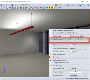
Default display of both direct and interreflected light (Composite)
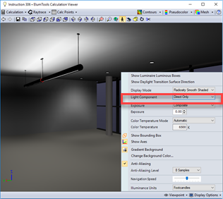
Display of direct light component only
Display of interreflected light component only
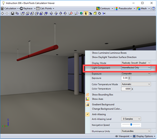
The ElumTools Calculation viewer default display shows the rendered result of the complete global illumination solution of both direct and interreflected light. Using the Light Component setting in Display Properties will allow you to visualize the rendered scene with only direct light (by removing all reflected light), or with only interreflected light (indirect light only, by removing the direct component). This can be very handy for designers demonstrating the visual effect of less or more direct or interreflected light.
If you have the illuminance points enabled, the calculated values will also change to display the selected mode. Pseudocolor mode can also be used to quantify the amount of light on surfaces due to direct or interreflected light alone.
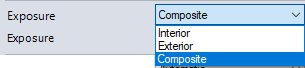
The ElumTools calculation viewer provides an Exposure adjustment for the rendered image to allow you to subjectively tune your visualization to meet your expectations. This is necessary to compensate for the limited contrast ratio of computer displays and the inherent assumptions used for the default rendered image.
The default is Composite. This is the same as the Interior setting when only interior electric lighting is considered. When the scene includes both Daylight and electric light you have the option to shift the exposure to exterior to properly expose the daylight scene or interior to properly expose the interior scene.
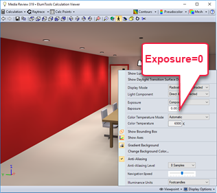
Exposure = 0 (default)
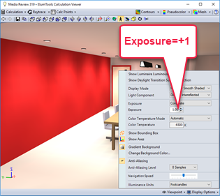
Exposure = +1
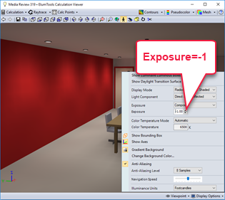
Exposure = -1
For the purposes of default rendered exposure (Exposure=0), ElumTools assumes the average scene reflectance for the rendered environment to be 18% gray (based on Eastman Kodak photographic research). This is clearly an average case for most architectural environments. Typical commercial interiors tend to be more reflective, while exterior surfaces (such as asphalt) will be less reflective.
In order to compensate for this standard photographic assumption, the display of light colored environments will benefit from a higher Exposure setting, while low-reflectance environments will appear more accurate with a lower Exposure.
- For the default display, the average reflectance of all pixels in the environment (regardless of current viewpoint) is calculated and re-calibrated to 18%. This is equivalent to an Exposure setting of 0.
- For every 1 point increase in Exposure the average scene reflectance doubles. Example: an Exposure setting of 1 is equivalent to an average scene reflectance of 36%.
- For every 1 point decrease in exposure, the average scene reflectance is cut in half. Example: an exposure of -1 is equivalent to an average scene reflectance of 9%.
- Most interiors will look more realistic with an Exposure setting between 0.75 and 1.5 (30 - 50% reflective).
- Most exteriors will look more realistic with an Exposure setting between -1.5 and 0 (6 - 18% reflective).
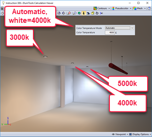
Automatic - ElumTools sets the white point of the display by the weighted average of all lumens of various color temperatures emitted in the space (all luminaires).
Default - The default color temperature for the white point of the ElumTools display is 6500k.
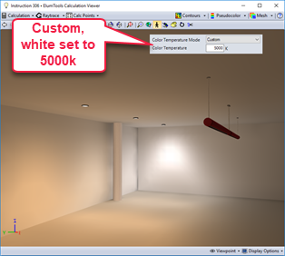
Custom - You can calibrate the display to your own white point preference using the Custom setting. Enter the default temperature in the cell below.
Displays the color temperature used for the white point of the display based on the setting above.
Important - Color Temperature must be enabled in Settings.
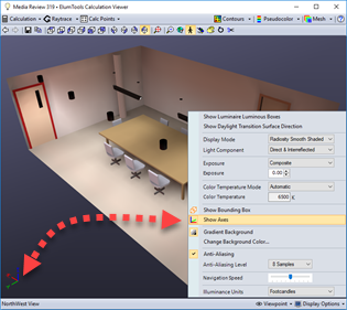 Display of viewer Cartesian axis
The ElumTools Calculation viewer shows a small Cartesian coordinate marker in the lower-left corner of the display. Its location does not mark the origin; it is simply a reference for relative direction and may be useful when manually editing the Viewpoint.
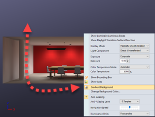
Gradient background
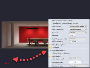
Solid background color
The default background for the rendered image is a purple-gray color with gradient from bottom (darkest) to top (lightest). We feel this enhances the rendered image. A Solid background of the same color can be selected if you prefer. The background color can be changed at will (see below) and a gradient or solid version of the new color displayed using these settings.
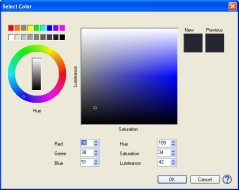
Default background color shown
Background color can be specified by entering RGB or HSL values manually, or by simply selecting a Hue from the circle (mouse click or drag) and then adjusting the Luminance and Saturation of that Hue by dragging the mouse around the large rectangle.
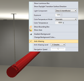
Anti-Aliasing enabled (notice pendant)
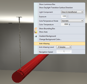
Anti-Aliasing disabled (notice pendant)
Anti-aliasing is a computer graphics process used to reduce the jagged appearance of rendered edges that are neither straight across nor straight up and down the screen. As your computer screen presents information in the form of pixels, diagonal lines (edges) will appear somewhat jagged. The anti-aliasing process finds edges and applies a sampling algorithm to smudge or blur the edges by blending the adjacent colors. When zoomed in very close, the effect is visible. However, when the image is viewed from a normal distance, the edges appear to be straight.
ElumTools applies anti-aliasing only when navigation stops; the application is typically fast enough to elude detection.
Anti-aliasing is on by default.
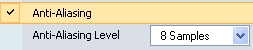
The higher the sampling level, the more blending occurs. The default sampling level is 8 which is adequate for most images.
